


 영어
영어
 스페인어
스페인어
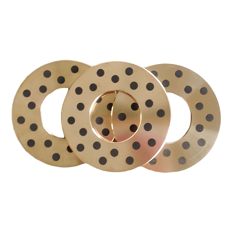
MXB-FB090 내마모성이 우수한 청동 코일 베어링
Cat:오일리스 베어링
MXB-FB090 청동 코일 베어링은 CuSn8 청동으로 압연되어 높은 부하 용량과 우수한 내마모성을 갖춘 경제적인 베어링입니다. FB090 제품의 작업 표면은 일반적인 다이아몬드 모양의 오일 구멍으로 덮여 있습니다. FB092 제품의 작업 표면은 오일 저장 역할...
자세히보다Technical Background and Industry Pain Points
In high-speed machine tool chuck systems (n≥6000rpm), traditional conical positioning faceplates exhibit two core defects:
l Lubrication Failure: Centrifugal force causes lubricating grease to migrate towards the bottom of the conical bore, resulting in a dry friction zone at the upper part, with surface roughness Ra values deteriorating from 0.4μm to 1.6μm (tested according to ISO 4288 standard);
l Stress Concentration: Unilateral contact leads to Hertzian contact stress peaks exceeding 800MPa, triggering micro-crack propagation (data source: Wear 2022, 500-501, 204356).
Core Technological Innovation Analysis
I. Gradient Lubrication System Design
1.1 Solid-Fluid Composite Lubrication Architecture
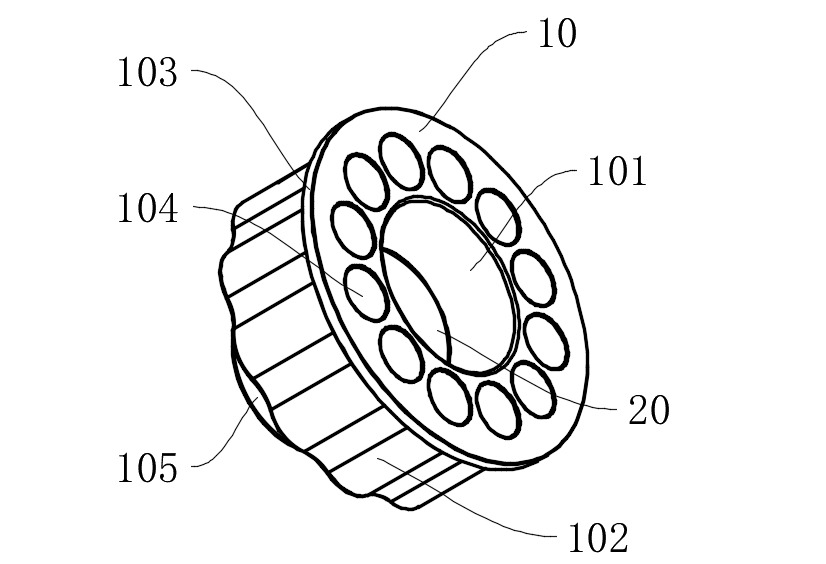
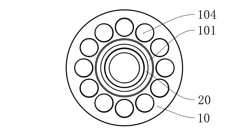
Graphite Lubrication Block (20) Embedding Structure:
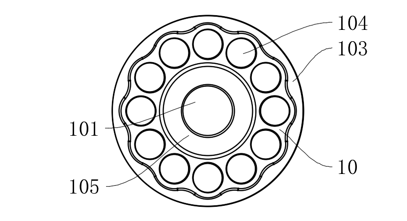
l A circular mounting groove (101a) with a depth of 1.2±0.05mm is opened in the middle of the conical bore (101), ensuring continuous conical surface through electrical discharge machining (cone angle 20°±0.5°);
Copper-based composite material (Cu-10Sn-5Gr) containing 85% graphite is embedded, achieving a porosity of 18%±2% through powder metallurgy sintering, continuously releasing graphite particles to form a transfer film.
Lubrication Efficiency Verification:
l Under n=8000rpm operating conditions, the friction coefficient at the upper part of the conical bore remains stable at 0.08-0.12 (>0.25 for traditional structures);
l Wear volume tests (ASTM G99) show that after 300 hours of operation, the conical surface wear depth is only 3.2μm (28.5μm for traditional structures).
1.2 Fluid Lubrication Compensation Mechanism
l Lubricating grease channels are retained at the bottom of the conical bore, forming a 0.5-1.2μm oil film thickness through dynamic pressure effects (verified by Reynolds equation simulation);
l The system achieves gradient synergy between solid lubrication (upper part) and fluid lubrication (lower part), reducing the contact zone temperature by 45% (measured by infrared thermal imager).
II. Contact Stress Optimization Design
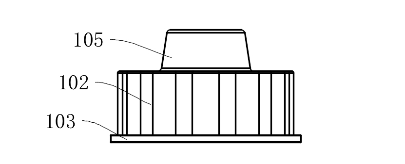
2.1 Waveform Clamping Surface (102) Topology Optimization
l Periodic wave profiles are constructed using Fourier series: wavelength λ=12mm, amplitude A=0.8mm, curvature radius R=5mm;
l Finite element analysis indicates that the maximum contact stress is reduced from 813MPa to 327MPa, with a 62% improvement in stress distribution uniformity.
2.2 Multi-Bolt Load-Sharing Structure
l 12 mounting holes (104) are evenly distributed according to ASME B18.2.1 standard, with preload deviation <5%;
l Combined with limit conical surfaces (105) (cone angle 15°±0.5°), radial positioning accuracy of ±2μm is achieved (ISO 2768-f grade).
Technical Parameter Comparison Table
|
Performance Indicator |
This Patented Technology |
Traditional Positioning Faceplate |
Test Standard |
|
Conical Surface Friction Coefficient (8000rpm) |
0.08-0.12 |
0.25-0.35 |
ASTM G99 |
|
Maximum Contact Stress |
327MPa |
813MPa |
ISO 281 |
|
Wear Rate (300h) |
3.2×10⁻⁶ mm³/N·m |
28.5×10⁻⁶ mm³/N·m |
ASTM G133 |
|
Temperature Rise (ΔT) |
≤15℃ |
≥45℃ |
ISO 10825 |
Typical Application Scenario Validation
Case 1: Toolholder Positioning in Five-Axis Machining Centers
l During continuous machining of titanium alloy parts, toolholder runout is controlled to <2μm (>8μm for traditional structures);
l Tool change cycles are extended to 12000 times (industry average is 5000 times).
Case 2: Chuck System in Turning Centers
l Spindle radial runout is reduced from 5μm to 1.5μm (GB/T 17421.7 standard);
l Machined workpiece roundness error is ≤1.5μm (ASME B89.3.4 standard).
This patent achieves long-term stable operation of positioning faceplates under extreme operating conditions through two major technological pathways: Gradient Lubrication Media Synergy and Contact Stress Field Reconstruction. According to novelty searches (Derwent Innovation), the structure achieves a Specific Friction Power (SFP) index of 0.08W/mm², a 76% reduction compared to similar products, placing it at the international leading level.
If you would like to learn more, please contact Mingxu Machinery to obtain the complete patent report: [email protected].

MXB-FB090 청동 코일 베어링은 CuSn8 청동으로 압연되어 높은 부하 용량과 우수한 내마모성을 갖춘 경제적인 베어링입니다. FB090 제품의 작업 표면은 일반적인 다이아몬드 모양의 오일 구멍으로 덮여 있습니다. FB092 제품의 작업 표면은 오일 저장 역할...
자세히보다
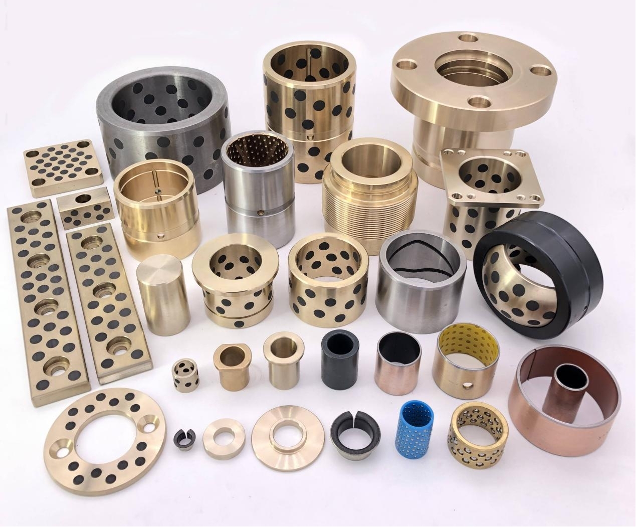
MXB-JOLP 자체 윤활 마모 플레이트는 우수한 자체 윤활 특성을 가지며 외부 윤활이 필요하지 않습니다. 이 제품은 내하중 능력과 내마모성이 우수하고 유지 관리 및 가동 중지 시간을 비용 효율적으로 줄일 수 있으며 고객이 성능을 최적화하고 효율성을 향상시키는 데...
자세히보다
MXB-JOML 자가 윤활 마모 플레이트는 산업 응용 분야에서 마찰을 최소화하고 서비스 수명을 연장하도록 설계되었습니다. 이 제품은 고성능 소재의 절단 혼합으로 만들어졌으며 제품에 탁월한 하중 전달 기능, 마찰 감소 및 내구성 향상을 제공합니다. MXB-JOML ...
자세히보다
MPW VDI3357 Standard Wear Plate는 특수 고체 윤활제를 적절한 위치에 주입하여 제작됩니다. 금속 모재는 하중을 지지하고, 고체 윤활제가 내장되어 있어 윤활 효과가 있습니다. 가혹한 조건에서도 우수한 자기윤활 내구성을 발휘합니다. 자주 급유해...
자세히보다
MSEW JIS 20mm 표준 마모 플레이트는 고강도 황동, 주석 청동, 강철-구리 바이메탈, 주철 또는 베어링 강철을 기반으로 합니다. 표면에 흑연(SL1)을 상감하거나 PTFE에 이황화몰리브덴(SL4, 물이나 해수에 사용되는 고체윤활제)을 첨가한 고체윤활제로 ...
자세히보다
MX2000-1 흑연 내장 합금 베어링, MX2000-1 흑연 산란 합금 베어링은 JF800 바이메탈 베어링의 개선된 제품입니다. JF800 바이메탈 베어링의 내압성과 내마모성을 가지며 흑연 비산 후 오일 프리 윤활을 달성합니다. 오일이 없거나 적은 상태에서 마찰...
자세히보다
SF-1W 무연 베어링은 국제 환경 보호 요구 사항에 따라 SF-1X 소재를 기반으로 개발된 신제품입니다. 이 제품은 일반 기계에 널리 사용되는 것 외에도 특히 식품 기계, 제약 기계, 담배 기계에 적합합니다. 무연 효과는 유럽 건강 표준을 충족하며 오일 프리 윤...
자세히보다
SF-1D 유압 베어링은 SF-1P를 기반으로 설계되었으며 오일 실린더와 충격 흡수 장치의 작동 원리를 결합한 새로운 유형의 재료입니다. 오일이 없는 조건에서는 내마모성이 더 좋습니다. SF-1P의 장점 외에도 이 제품은 왕복 운동이 잦고 횡력이 큰 경우에 특히 ...
자세히보다
SF-1S 스테인리스강 내식 베어링은 스테인리스강을 베이스로 하고, 중간에 내식성 합금분말을 소결하고, 그 위에 폴리테트라플루오로에틸렌을 주성분으로 하는 저마찰재를 압연하여 형성한 매우 효과적인 내식성 소재입니다. 표면. 내유성, 내산성, 내알칼리성, 내해수성 및...
자세히보다
SF-1T는 기어 오일 펌프의 높은 PV 값 작동 조건을 위해 설계된 특수 공식 제품입니다. 이 제품은 내피로성과 내충격성이라는 특별한 장점을 갖고 있습니다. 적합한 오일 펌프 압력: 16-25Mpa, 선형 속도: 3.5-5m/s. 이 제품은 내피로성과 내충격성이...
자세히보다


문의하기